
hydropower turbine propeller:
- Part 1: Parameters and operating parts of a turbine system.
- Part 2: The relation stator guide vanes and propeller
- Part 3: The design method of hydraulic turbine
- Part 4: Tutorial designing a turbine system.
- Tutorial hydroelectric turbine design 1/3 :Site power and turbine design
- Tutorial hydroelectric turbine design 2/3 :Design :guide vanes or stator
- Tutorial hydroelectric turbine design 3/3 :Choice sections, design draft tube
Tutorial hydroelectric turbine design 3/3 :Choice sections, design draft tube:
- Reminder of the rules guiding the choice of sections
- Adduction area
- Guide vanes and turbine area
- diffuser draft vacuum tube area
Reminder of the rules guiding the choice of sections:
We have seen that there are two basic rules that justify the choice of sections:" Minimize pressure losses and minimize the cost of parts by concentrating energy" and these 2 rules, respectively lead to an increase and a decrease of the dimensions.
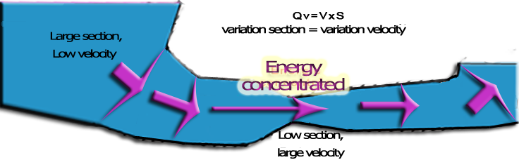
We have seen that the energy losses are important if:
- The fluid velocity is high and the roughness is important
- Speed variation due to the change of section is important and sudden
- the change of direction is important and sudden


and that these energy losses will therefore be minimal if:
- the speed is low and surfaces are smooth
- the speed variation due to a change in section is gradual and low
- the change of direction is low and progressive


Adduction Area
We will evaluate for example, the pressure loss of a convergent cone from 3 meters to 1.9 meters at 30 degrees, for a rate of 8m3/sec:
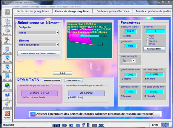
We get a head loss of 25 mm for the inlet cone.
Guide vanes and turbine area
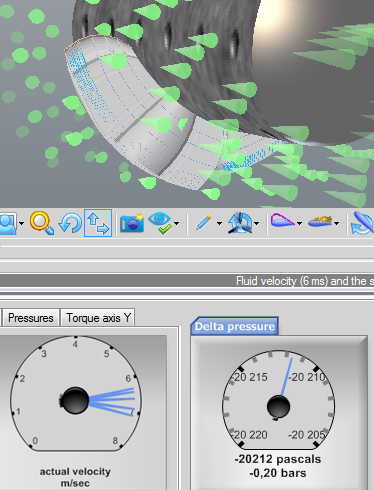
We have calculated the loss of the stator vanes or guide in the previous chapter about the calculation of stator vanes or guide: We got 0.7 meter pressure loss in the guide vanes stator. At the beginning of the previous chapter (calculation of stator vanes or guide) we calculated our propeller with Heliciel introducing a tangential flow of 4.4 rad / sec. In the results area, we have access to the pressure difference generated between the upstream and downstream of the propeller. This pressure difference gives us the "pressure loss" generated by the turbineWhat gives with the pressure value measured in Heliciel: 20339 =(we will remember for simplicity that 1 bar = 10 meters of water so 0.2 bars = 2 meters of head losses)
(delta pressure upstream downstream turbine)
So we will estimate the height of load required for the crossing of the turbine to the operating point calculated: 2 metersTotal pressure loss consumed by the guide vanes and turbine Area = 0.7 2 = 2.7 meters
Gross height available is 4 meters, we could generate more tangential flow with our distributor (This is an information for optimization and adjustment of the vanes of the distributor)
- Accompanying the change in velocity induced
Before defining the vacuum (diffuser, draft tube),we must take into account the relationship between volume, speed and flow rate for an incompressible fluid. We have a volume flow 12 m3/sec that through our system. Due to the compressibility of our fluid,the inlet flow rate is identical to the output flow.We can even establish that the section is related to the speed by law::To avoid uncontrolled changes speeds which will translate by losses, it is important to check the sections according to the desired speed or estimated in the different parts of the system.
- axial velocity(m/sec) = rate of flow (m3/sec) / section (m²)
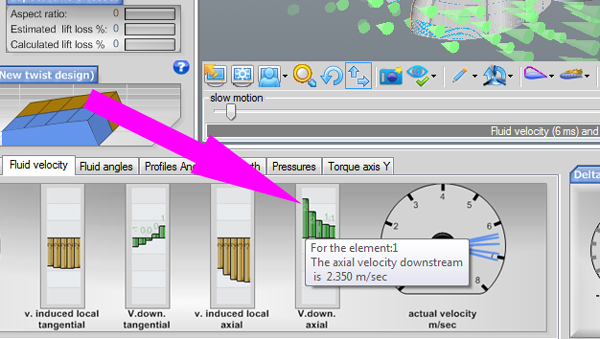
In the results area of software HELICIEL, select the tab "fluid velocities". We can see the axial velocity downstream (output propeller). The relation: axial velocity(m/sec) = rate of flow (m3/sec) / section (m²), therefore gives the section that should be our conduct at turbine outlet to accompany speed change caused by the turbine, with no additional disturbance:
Section output turbine:
- axial velocity(m/sec) = rate of flow (m3/sec) / section (m²)
- => section (m²) = Débit (m3/sec) /Vitesse axiale(m/sec)
area diffuser, draft tube:
We saw in Chapter turbine design, that the kinetic energy can not be fully captured by a propeller as this would completely stop the flow at the output and to have an infinite volume of fluid stokage, at the outlet point of the turbine..it is possible to expand the sections to approach a very low speed. It is 40% of the kinetic energy of axial velocity at the turbine outlet. This speed energy can be recovered and converted into local depression at the outlet of the turbine, with a variation of regular section.
draft tube
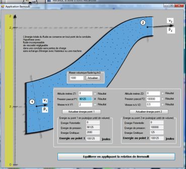
If a vacuum is generated at the turbine outlet, this will result (depending on Bernoulli's Theorem) to increase the rate of passage of turbine and generating a power gain. So we will create a diverging conical vacuum, which will locate a depression, to turbine output by varying its section(Thus the fluid velocity)between its input and outlet. If this speed change is too abrupt, we will create a loss of energy by turbulence and the draft tube will not be very effective. The optimum cone angle generating the speed variation with minimal losses is approximately 6°, but for reasons of economy of material and space, cones of draft tubes are about 12 degrees.Tip: The calculation of the depression created by the draft tube can be done with the application of Bernoulli mecaflux software:
Enter Data:
- Density: water 1000 kg/m3
- Point 1:
- Altitude: we will not consider here the altitude and we set 0.
- Pressure inlet draft tube(point 1): check "result" because it is the value we are looking for
- Inlet draft tube speed(turbine outlet):The speed at the turbine outlet is found in the result field of software héliciel. Nous prendrons une valeur moyenne de 2 m/sec
- Point 2:
- Altitude: set 0.
- Pressure outlet draft tube(point 2): this is the output in the open air in the basin so 100000(atmospheric pressure)
- outlet draft tube speed(point2): The output speed is estimated according to the flow of our system (12m3/s)section divided by the maximum that we can achieve, taking into account the price constraints and dimensions complying with a minimum angle of cone (around 10 to 12 degrees usually)
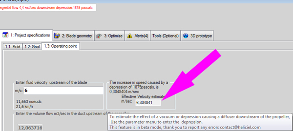
Nous avons estimé ici que le diffuseur pourra réaliser une variation de vitesse de 2 m/sec à 0.5 m/sec.We estimated that ledraft tube can realize speed variation, from 2 m / sec to 0.5 m / sec. This generates a pressure at the inlet of the draft tube, of 98125, so a depression :98125-100000 =1875 pascals:
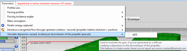
With héliciel we resume our propeller to evaluate the gain in power caused by the depression located downstream of the propeller,we use the parameter menu / simulate depression located downstreamand by enter the value of 1875 Pascals:
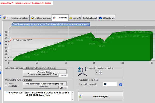
The Optimum speed and power is increased by the suction parameter:
We conclude this small tutorial here, but it is obvious that we could further optimize our system, including the increase of tangential introduction to our Central are perfectly suited to the site.
hydropower turbine propeller:
- Part 1: Parameters and operating parts of a turbine system.
- Part 2: The relation stator guide vanes and propeller
- Part 3: The design method of hydraulic turbine
- Part 4: Tutorial designing a turbine system.
- Tutorial hydroelectric turbine design 1/3 :Site power and turbine design
- Tutorial hydroelectric turbine design 2/3 :Design :guide vanes or stator
- Tutorial hydroelectric turbine design 3/3 :Choice sections, design draft tube
 Global site map
 Mecaflux
 Tutorials Mecaflux Pro3D
 Tutorials Heliciel
 Mecaflux Store
 Quotes, Orders, Payment Methods
 project technical studies